
【FPGA】Verilog 实践:奇偶校验生成器 | 奇偶校验检查器 | 2-bit 二进制比较器
写在前面:Parity bit Generator/Checker 和 2bit binary comparator 的了解和确认动作。使用Verilog 进行 Parity bit Generator/Checker、2bit binary,实施 comparator,生成输入信号后确认通过模拟器实现的每个 Gate 操作,通过 FPGA 验证 Verilog 实现的电路的行为。
Ⅰ. 前置知识
0x00 Parity bit 生成器
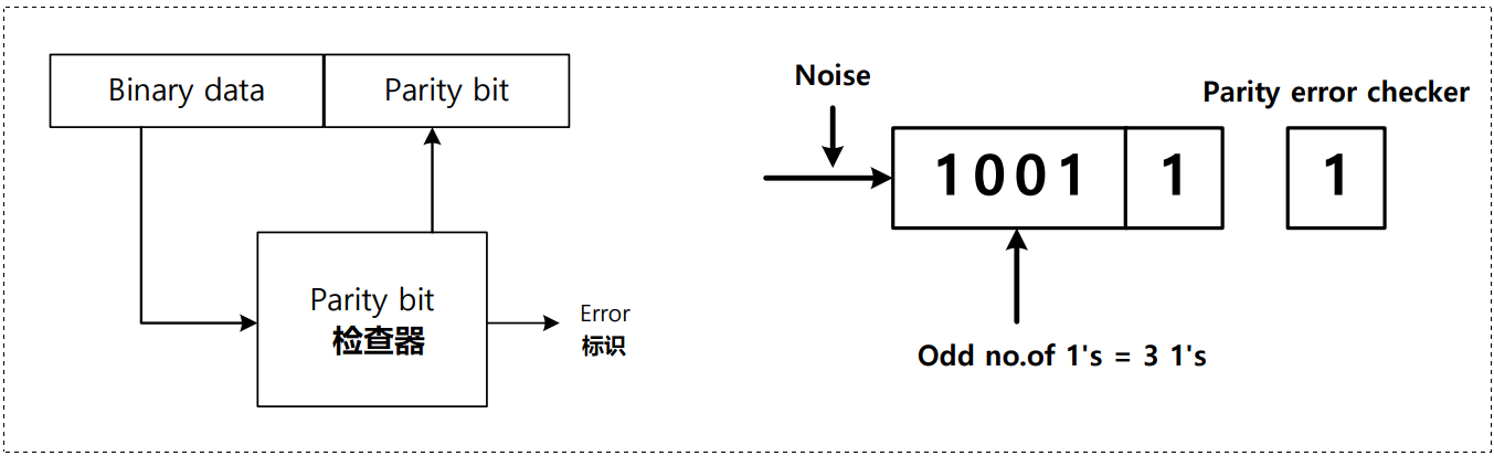
传输二进制信息时使用 parity bit 来检测error。
在发送二进制数据时,增加一个称为 parity bit 的 1-bit 作为发送方法,如果 binary 数据的 1bit 的数目是奇数,则 parity bit 为 1,如果 1bit 的数目是偶数,则 parity bit 为 0。因此,总体上总是具有偶数个 1bit 的传输数据形式,从而将其传输到目的地。

0x01 Parity bit 检查器
在接收器中检查奇偶校验的电路称为奇偶校验器。
奇偶校验校验器的输出用奇偶校验()表示,如果1为奇数(如果有错误),则为1;如果1为偶数或0,则
为 0。
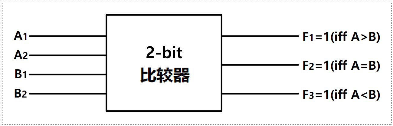
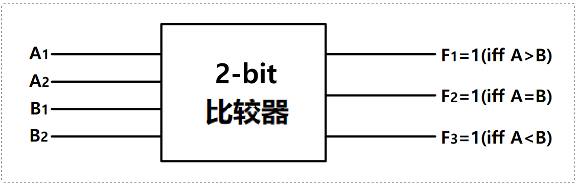
0x02 2-bit 二进制比较器
当有 2-bit 二进制数 时,如果
则输出
;如果
,则输出
;如果
,则输出
为 1,组合逻辑电路。
Ⅱ. 练习(Assignment)
0x00 实现 Parity bit 生成器
画出卡诺图完成真值表,编写 Verilog 代码,通过 Simulation 打印出结果(8,4,2,1)

真值表:
| In A | In B | In C | In D | Out E |
| 0 | 0 | 0 | 0 | 0 |
| 0 | 0 | 0 | 1 | 1 |
| 0 | 0 | 1 | 0 | 1 |
| 0 | 0 | 1 | 1 | 0 |
| 0 | 1 | 0 | 0 | 1 |
| 0 | 1 | 0 | 1 | 0 |
| 0 | 1 | 1 | 0 | 0 |
| 0 | 1 | 1 | 1 | 1 |
| 1 | 0 | 0 | 0 | 1 |
| 1 | 0 | 0 | 1 | 0 |
| 1 | 0 | 1 | 0 | 0 |
| 1 | 0 | 1 | 1 | 1 |
| 1 | 1 | 0 | 0 | 0 |
| 1 | 1 | 0 | 1 | 1 |
| 1 | 1 | 1 | 0 | 1 |
| 1 | 1 | 1 | 1 | 0 |
卡诺图:
| ab cd | 00 | 01 | 11 | 10 |
| 00 | 0 | 1 | 0 | 1 |
| 01 | 1 | 0 | 1 | 0 |
| 11 | 0 | 1 | 0 | 1 |
| 10 | 1 | 0 | 1 | 0 |
💬 Design source:
`timescale 1ns / 1ps

module parity_bit_generator(
    input a, b, c, d,
    output e
    );

    assign e = a ^ b ^ c ^ d;

endmodule
💬 Testbench:
`timescale 1ns / 1ps

module parity_bit_generator_tb;
reg aa, bb, cc, dd;
wire e;

parity_bit_generator u_parity_bit_generator(
   .a(aa),
   .b(bb),
   .c(cc),
   .d(dd),
   .e(e)
   );

initial aa = 1'b0;
initial bb = 1'b0;
initial cc = 1'b0;
initial dd = 1'b0;

always aa = #100 ~aa;
always bb = #200 ~bb;
always cc = #400 ~cc;
always dd = #800 ~dd;

initial begin
  #1000
  $finish;
end

endmodule
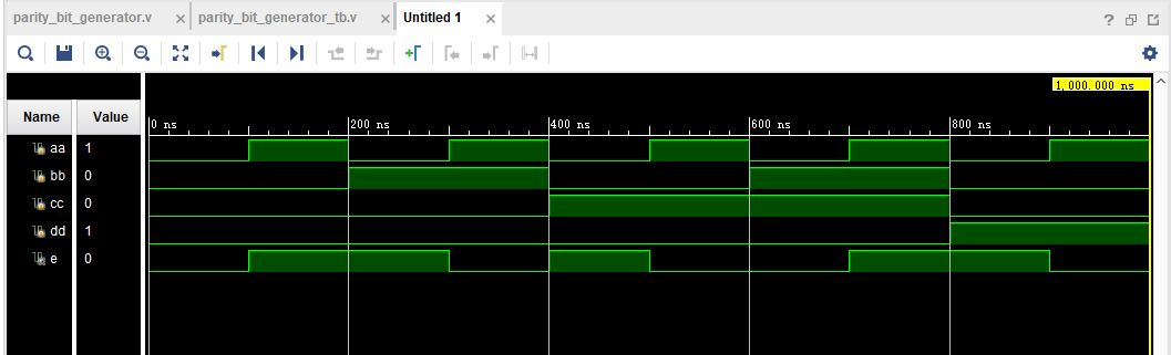
🚩 运行结果如下:
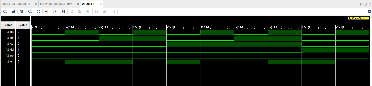
0x01 实现 Parity bit 检查器
画出卡诺图完成真值表,编写 Verilog 代码,通过 Simulation 打印出结果(8,4,2,1)

真值表:
| In A | In B | In C | In D | Out E |
| 0 | 0 | 0 | 0 | 0 |
| 0 | 0 | 0 | 1 | 1 |
| 0 | 0 | 1 | 0 | 1 |
| 0 | 0 | 1 | 1 | 0 |
| 0 | 1 | 0 | 0 | 1 |
| 0 | 1 | 0 | 1 | 0 |
| 0 | 1 | 1 | 0 | 0 |
| 0 | 1 | 1 | 1 | 1 |
| 1 | 0 | 0 | 0 | 1 |
| 1 | 0 | 0 | 1 | 0 |
| 1 | 0 | 1 | 0 | 0 |
| 1 | 0 | 1 | 1 | 1 |
| 1 | 1 | 0 | 0 | 0 |
| 1 | 1 | 0 | 1 | 1 |
| 1 | 1 | 1 | 0 | 1 |
| 1 | 1 | 1 | 1 | 0 |
卡诺图:
| ab cd | 00 | 01 | 11 | 10 |
| 00 | 0 | 1 | 0 | 1 |
| 01 | 1 | 0 | 1 | 0 |
| 11 | 0 | 1 | 0 | 1 |
| 10 | 1 | 0 | 1 | 0 |
💬 Design source:
`timescale 1ns / 1ps

module parity_bit_checker(
    input a,b,c,d,p,
    output e
    );

    assign e = a^b^c^d^p;

endmodule
💬 Testbench:
`timescale 1ns / 1ps

module parity_bit_checker_tb;
reg aa, bb, cc, dd, pp;
wire e;

parity_bit_checker u_parity_bit_checker(
    .a(aa),
    .b(bb),
    .c(cc),
    .d(dd),
    .p(pp),
    .e(e)
    );

initial aa = 1'b0;
initial bb = 1'b0;
initial cc = 1'b0;
initial dd = 1'b0;
initial pp = 1'b0;

always aa = #100 ~aa;
always bb = #200 ~bb;
always cc = #400 ~cc;
always dd = #800 ~dd;
always pp = #1600 ~pp;

initial begin
   #2000
   $finish;
end

endmodule
🚩 运行结果如下:
0x02 实现 2-bit 二进制比较器
画出卡诺图完成真值表,编写 Verilog 代码,通过 Simulation 打印出结果(8,4,2,1)
真值表:
| In A | In B | In C | In D | Out F1 | Out F2 | Out F3 |
| 0 | 0 | 0 | 0 | 0 | 1 | 0 |
| 0 | 0 | 0 | 1 | 0 | 0 | 1 |
| 0 | 0 | 1 | 0 | 0 | 0 | 1 |
| 0 | 0 | 1 | 1 | 0 | 0 | 1 |
| 0 | 1 | 0 | 0 | 1 | 0 | 0 |
| 0 | 1 | 0 | 1 | 0 | 1 | 0 |
| 0 | 1 | 1 | 0 | 0 | 0 | 1 |
| 0 | 1 | 1 | 1 | 0 | 0 | 1 |
| 1 | 0 | 0 | 0 | 1 | 0 | 0 |
| 1 | 0 | 0 | 1 | 1 | 0 | 0 |
| 1 | 0 | 1 | 0 | 0 | 1 | 0 |
| 1 | 0 | 1 | 1 | 0 | 0 | 1 |
| 1 | 1 | 0 | 0 | 1 | 0 | 0 |
| 1 | 1 | 0 | 1 | 1 | 0 | 0 |
| 1 | 1 | 1 | 0 | 1 | 0 | 0 |
| 1 | 1 | 1 | 1 | 0 | 1 | 0 |
卡诺图:
A>B
| ab cd | 00 | 01 | 11 | 10 |
| 00 | 0 | 0 | 0 | 0 |
| 01 | 1 | 0 | 0 | 0 |
| 11 | 1 | 1 | 0 | 1 |
| 10 | 1 | 1 | 0 | 0 |
A=B
| ab cd | 00 | 01 | 11 | 10 |
| 00 | 1 | 0 | 0 | 0 |
| 01 | 0 | 1 | 0 | 0 |
| 11 | 0 | 0 | 1 | 1 |
| 10 | 0 | 0 | 0 | 1 |
A<B
| ab cd | 00 | 01 | 11 | 10 |
| 00 | 0 | 1 | 1 | 1 |
| 01 | 0 | 0 | 1 | 1 |
| 11 | 0 | 0 | 0 | 0 |
| 10 | 0 | 0 | 1 | 0 |
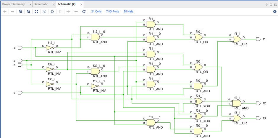
💬 Design source:
`timescale 1ns / 1ps

module two_bit_binary_comparator(
    input a, b, c, d,
    output f1, f2, f3
    );

    assign f1 = (a & ~c) | (b & ~c & ~d) | (a & b & ~d);
    assign f2 = ~(a ^ c) & ~(b ^ d);
    assign f3 = (~a & c) | (~a & ~b & d) | (~b & c & d);

endmodule
💬 Testbench:
`timescale 1ns / 1ps

module two_bit_binary_comparator_tb;
 reg aa, bb, cc, dd;
 wire f1, f2, f3;

two_bit_binary_comparator u_two_bit_binary_comparator(
    .a(aa),
    .b(bb),
    .c(cc),
    .d(dd),
    .f1(f1),
    .f2(f2),
    .f3(f3)
    );

initial aa = 1'b0;
initial bb = 1'b0;
initial cc = 1'b0;
initial dd = 1'b0;

always aa = #100 ~aa;
always bb = #200 ~bb;
always cc = #400 ~cc;
always dd = #800 ~dd;

initial begin
   #1000
   $finish;
end

endmodule
🚩 运行结果如下:


📌 [ 笔者 ]   王亦优 / akam
📃 [ 更新 ]   2023.2.6
❌ [ 勘误 ]   /* 暂无 */
📜 [ 声明 ]   由于作者水平有限,本文有错误和不准确之处在所难免,
本人也很想知道这些错误,恳望读者批评指正!| 📜 参考资料 Introduction to Logic and Computer Design, Alan Marcovitz, McGrawHill, 2008 Microsoft. MSDN(Microsoft Developer Network)[EB/OL]. []. . 百度百科[EB/OL]. []. https://baike.baidu.com/. |
相关文章
- 将Model对象转换成json文本或者json二进制文件
- java跨平台、对话框、二进制数据打印
- c#常用工具类:文件和二进制转换
- Java实现二进制幂
- 重新点亮linux 命令树————二进制安装[十一八]
- Centos7 k8s v1.5.2二进制部署安装-服务发现
- C++整数转二进制
- LeetCode-67. 二进制求和【位运算,字符串,数学,模拟】
- 如何正确地把服务器端返回的文件二进制流写入到本地保存成文件
- 剑指 Offer II 003. 前 n 个数字二进制中 1 的个数-c语言常规做法
- 练习 2-7 编写一个函数invert(x, p, n),该函数返回对x执行下列操作后的结果值:将x中从第p位开始的n个(二进制)位求反(即,1变成0,0变成1),x的其余各位保持不变。
- C++ 判断文件内容是二进制还是ASCII
- kubernetes 二进制安装(v1.20.15)(九)收尾:部署几个仪表盘
- kubernetes 二进制安装(v1.20.15)(七)加塞一个工作节点
- 格雷码与二进制的转换
- 4. 二进制数据处理库
- 二进制代码逆向——如何寻找main入口,先找mainCRTStartup,common_main,common_main_seh,invoke_main,main然后就是main函数
- 5. 多重背包问题 II(背包模型+二进制优化)