
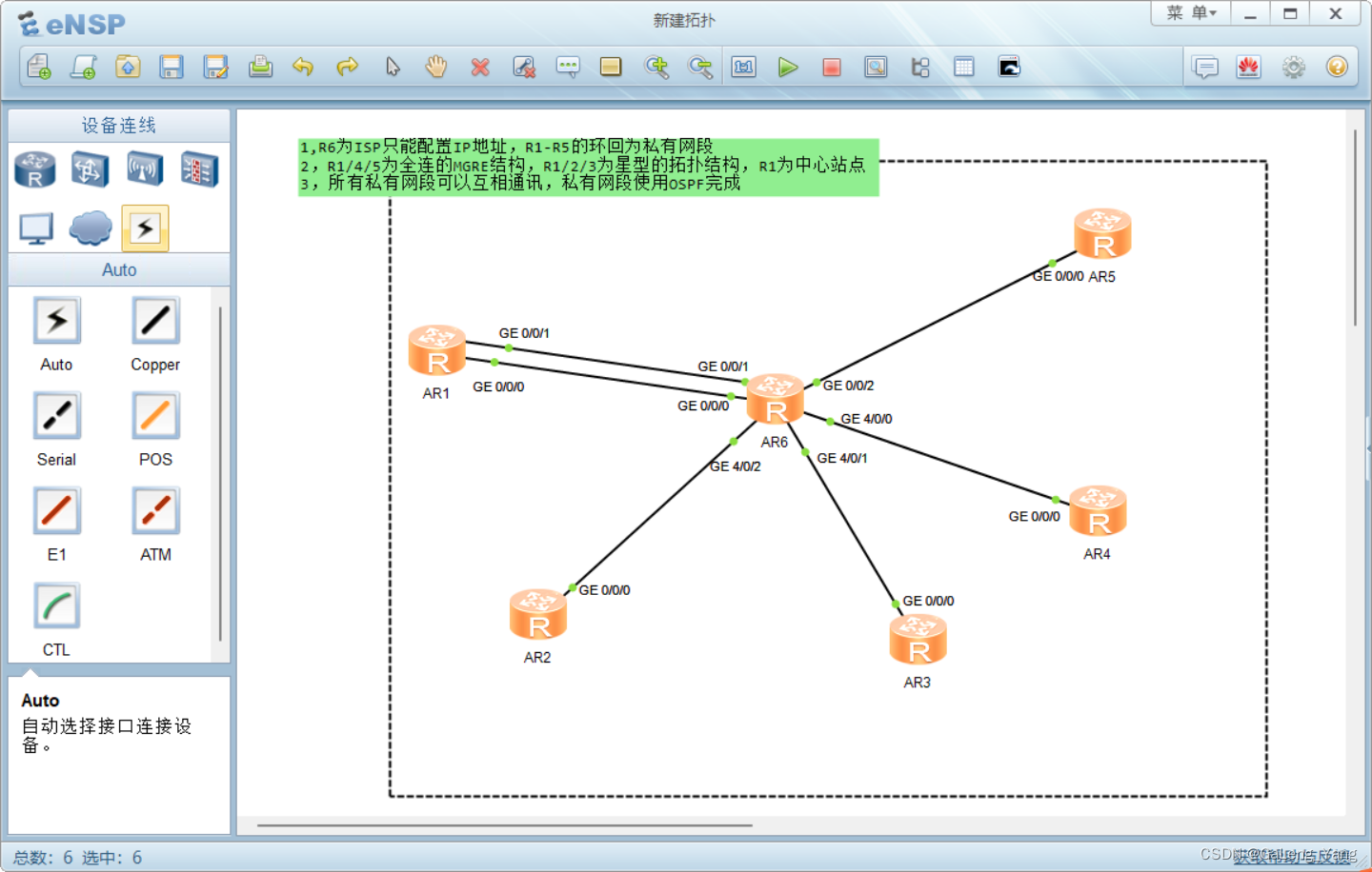
HCIP第五次实验—MGRE环境下的OSPF实验
第一步配置IP
R1
[r1-GigabitEthernet0/0/0]ip add 16.0.0.1 24
[r1-GigabitEthernet0/0/1]ip add 116.0.0.1 24
[r1-LoopBack0]ip add 192.168.1.1 24
R2
[r2-GigabitEthernet0/0/0]ip add 26.0.0.1 24
[r2-LoopBack0]ip add 192.168.2.1 24
R3
[r3-GigabitEthernet0/0/0]ip address 36.0.0.1 24
[r3-LoopBack0]ip add 192.168.3.1 24
R4
[r4-GigabitEthernet0/0/0]ip add 46.0.0.1 24
[r4-LoopBack0]ip add 192.168.4.1 24
R5
[r5-GigabitEthernet0/0/0]ip add 56.0.0.1 24
[r5-LoopBack0]ip add 192.168.5.1 24
R6
[r6isp-GigabitEthernet0/0/0]ip add 16.0.0.2 24
[r6isp-GigabitEthernet0/0/1]ip add 116.0.0.2 24
[r6isp-GigabitEthernet4/0/2]ip add 26.0.0.2 24
[r6isp-GigabitEthernet4/0/1]ip add 36.0.0.2 24
[r6isp-GigabitEthernet4/0/0]ip add 46.0.0.2 24
[r6isp-GigabitEthernet0/0/2]ip add 56.0.0.2 24
第二步,搭建HGRE环境 --- 写缺省
R1
[r1]ip route-static 0.0.0.0 0 16.0.0.2
[r1]ip route-static 0.0.0.0 0 116.0.0.2R2
[r2]ip route-static 0.0.0.0 0 26.0.0.2
R3
[r3]ip route-static 0.0.0.0 0 36.0.0.2
R4
[r4]ip route-static 0.0.0.0 0 46.0.0.2
R5
[r5]ip route-static 0.0.0.0 0 56.0.0.2
R6
公网以搭建完整
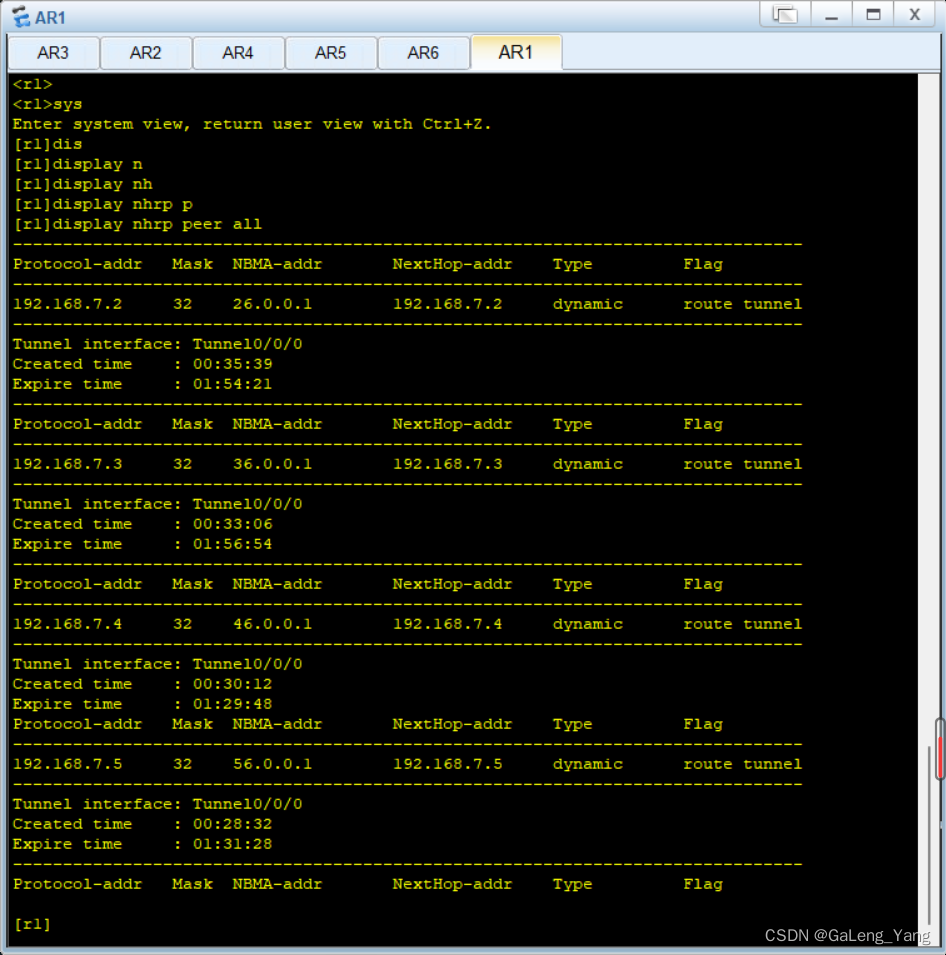
第三步,建立MGRE隧道中心和分支
R1/2/3为星型的拓扑结构,R1为中心站点
R1 --- 中心站点的配置
[r1]int t0/0/0
[r1-Tunnel0/0/0]ip add 192.168.7.1 24 隧道地址[r1-Tunnel0/0/0]tunnel-protocol gre p2mp 私网类型
[r1-Tunnel0/0/0]source 16.0.0.1 定义封装类型
[r1-Tunnel0/0/0]nhrp network-id 100
[r1-Tunnel0/0/0]nhrp entry multicast dynamic 开启伪广播
R2
[r2]int t0/0/0
[r2-Tunnel0/0/0]ip add 192.168.7.2 24
[r2-Tunnel0/0/0]tunnel-protocol gre p2mp
[r2-Tunnel0/0/0]source g 0/0/0
[r2-Tunnel0/0/0]nhrp network-id 100 ---加入到中心创建的NHRP域
[r2-Tunnel0/0/0]nhrp entry 192.168.7.1 16.0.0.1 register 注册到中心站点
R3
[r3]int t0/0/0
[r3-Tunnel0/0/0]ip add 192.168.7.3 24
[r3-Tunnel0/0/0]tunnel-protocol gre p2mp
[r3-Tunnel0/0/0]source g0/0/0
[r3-Tunnel0/0/0]nhrp network-id 100
[r3-Tunnel0/0/0]nhrp entry 192.168.7.1 16.0.0.1 register
R1 R1/4/5为全连的MGRE结构
[r1]int t0/0/1
[r1-Tunnel0/0/1]ip add 192.168.6.1 24
[r1-Tunnel0/0/1]tunnel-protocol gre p2mp
[r1-Tunnel0/0/1]source 116.0.0.1
[r1-Tunnel0/0/1]nhrp network-id 150 ---- 域可以重复也可不,不影响
[r1-Tunnel0/0/1]nhrp entry multicast dynamicR4
[r4]int t0/0/0
[r4-Tunnel0/0/0]ip add 192.168.6.4 24
[r4-Tunnel0/0/0]tunnel-protocol gre p2mp
[r4-Tunnel0/0/0]source 46.0.0.1 --- 固定的物理出接口
[r4-Tunnel0/0/0]nhrp network-id 150
[r4-Tunnel0/0/0]nhrp entry multicast dynamicR5
[r5]int t0/0/0
[r5-Tunnel0/0/0]ip add 192.168.6.5 24
[r5-Tunnel0/0/0]tunnel-protocol gre p2mp
[r5-Tunnel0/0/0]source 56.0.0.1
[r5-Tunnel0/0/0]nhrp network-id 150
[r5-Tunnel0/0/0]nhrp entry multicast dynamic------------------此时R1,R4,R5都承担中心角色,下面应充当分支角色进行汇报
R1
[r1-Tunnel0/0/1]nhrp entry 192.168.6.4 46.0.0.1 register 找R4汇报
[r1-Tunnel0/0/1]nhrp entry 192.168.6.5 56.0.0.1 register 找R5汇报
R4
[r4-Tunnel0/0/0]nhrp entry 192.168.6.1 116.0.0.1 register 找R1汇报 --- 没必要重复上报
因为R1向R4,R5上报后,R4和R5信息也到了R1上
[r4-Tunnel0/0/0]nhrp entry 192.168.6.5 56.0.0.1 register ---找R5汇报 这个需要配 R4没R5信息
R5 这两个汇报都没必要,原因同上
[r5-Tunnel0/0/0]nhrp entry 192.168.6.4 46.0.0.1 register 找R4汇报
[r5-Tunnel0/0/0]nhrp entry 192.168.6.1 116.0.0.1 register 找R1汇报
如图,R4 R5也类似
最后一步:3,所有私有网段可以互相通讯,私有网段使用OSPF完成
R1
[r1]ospf 1 router-id 1.1.1.1
[r1-ospf-1]a 0
[r1-ospf-1-area-0.0.0.0]network 1.1.1.0 0.0.0.255
[r1-ospf-1-area-0.0.0.0]network 192.168.7.0 0.0.0.255
[r1-ospf-1-area-0.0.0.0]network 192.168.6.0 0.0.0.255
[r1-ospf-1-area-0.0.0.0]network 192.168.1.0 0.0.0.25R2
[r2]ospf 1 router-id 2.2.2.2[r2-ospf-1]a 0
[r2-ospf-1-area-0.0.0.0]network 2.2.2.0 0.0.0.255
[r2-ospf-1-area-0.0.0.0]network 192.168.2.0 0.0.0.255R3
[r3]ospf 1 router-id 3.3.3.3
[r3-ospf-1]a 0
[r3-ospf-1-area-0.0.0.0]network 3.3.3.0 0.0.0.255
[r3-ospf-1-area-0.0.0.0]network 192.168.3.0 0.0.0.255R4
[r4]ospf 1 router-id 4.4.4.4
[r4-ospf-1]a 0
[r4-ospf-1-area-0.0.0.0]network 4.4.4.0 0.0.0.255
[r4-ospf-1-area-0.0.0.0]network 192.168.4.0 0.0.0.255R5
[r5]ospf 1 router-id 5.5.5.5
[r5-ospf-1]a 0
[r5-ospf-1-area-0.0.0.0]network 5.5.5.0 0.0.0.255
[r5-ospf-1-area-0.0.0.0]network 192.168.5.0 0.0.0.255 ------------ospf进程启动完毕但此时ospf为P2P网络 第二步两种环境R1各选取一个设备为邻居关系,舍弃另一种。
最好的解决方法:把接口的网络类型改为P2MP,可以建立多个邻居关系,不需要DR选举
R1,R2,R3修改p2mp
R1
[r1]int t0/0/0
[r1-Tunnel0/0/0]ospf network-type p2mp
R2
[r2]int t0/0/0
[r2-Tunnel0/0/0]ospf network-type p2mp
R3
[r3]int t0/0/0
[r3-Tunnel0/0/0]ospf network-type p2mp
R1,R4,R5修改broadcast
R1
[r1]int t0/0/0
[r1-Tunnel0/0/0]ospf network-type broadcast
R4
[r4]int t0/0/0
[r4-Tunnel0/0/0]ospf network-type broadcast
R5
[r5]int t0/0/0
[r5-Tunnel0/0/0]ospf network-type broadcast
实验完成!!!!!!!!!!!!!